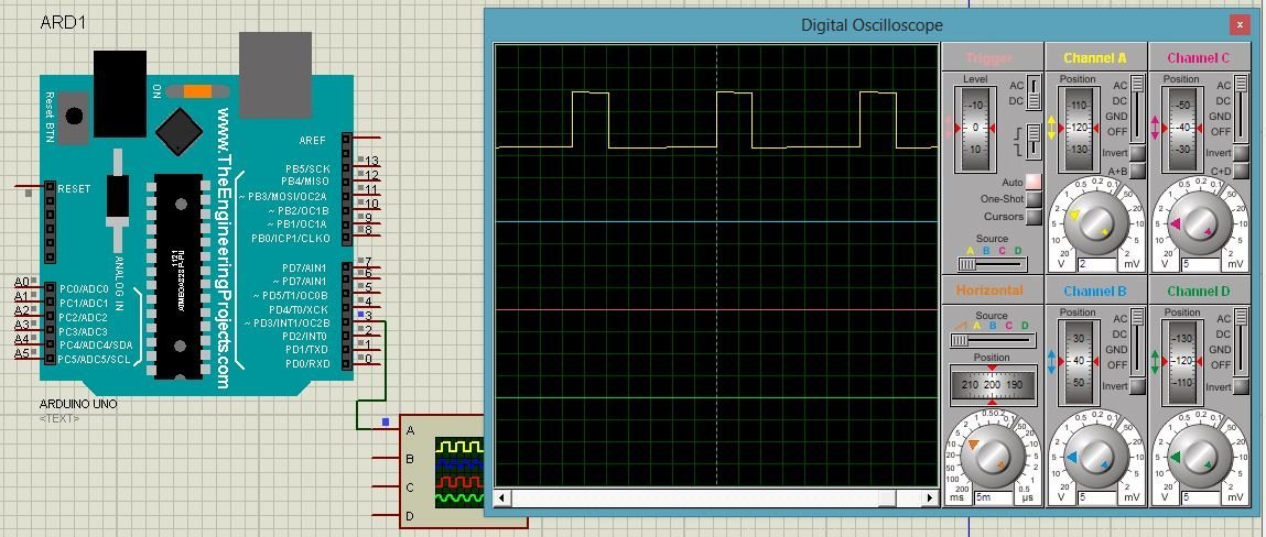

It is available in the File->Sketchbook->Examples->Analog menu of the Arduino software. The voltage levels are from 0 to 255 where 0 signifies a 0 duty cycle and a value of 255 signifies a 100 duty cycle. These voltage levels differ by 19.6 mV (5V/255) from the adjacent voltage levels. But instead of a mechanical switch, it features a third terminal called gate. It allows or interrupts the electric flow between its source and drain terminals.
ARDUINO PWM HOW TO
Calling the analogWrite() function allows a stable square wave with a specified duty cycle to be generated on the PWM pins. Mode 1 Normal 2 001 PWM, Phase Correct 3 010 CTC 4 011 Fast PWM 5 100 Reserved 6 101 PWM, Phase Correct 7 110 Reserved 111 Fast PWM Compare Output Mode. The Fading example demonstrates the use of analog output (PWM) to fade an LED. In Arduino the duty cycle of a pwm signal is controlled by an 8-bit register and therefore we can have 256 voltage levels between 0 and 5V. In this example, we will learn how to amplify Arduinos PWM capabilities. pin 3, 5, 6, 9, 10, 11) which can output a PWM wave with analogWrite() function.

It is an Arduino-compatible board, which is based on ATmega328P MCU You have remained in right site to start getting this info Controling DC motor with attiny2313 using PWM ok im using arduino mega 2560 to control the speed of a dc motor Order today, ships today I generally use 0b011 as that means I dont have to worry about the top value of the PWM cycle because its automatically 0xff (255 0b11111111) I. The default PWM frequency for all pins is 490 Hz, except pins 4 and 13 whose default frequency is 980Hz. These pins are numbered as 3, 5,6,9,10, and 11. The Seeeduino board is a good learning and evaluation board. On Arduino Nano, there are a total of 6 PWM pins available. PWM can be easily implemented in various ways on Arduino. Thus, a 100% duty cycle means the signal is always on (full-scale), and the 0% duty cycle means the signal is always off(grounding). It was originally designed for controlling the brightness of LEDs, but could be.
ARDUINO PWM SERIES
A Wiring Framework (and Arduino) Library, for Atmel AVR8 bit series microcontrollers and Teensy 3.x, to produce PWM signals on any arbitrary pin.
ARDUINO PWM SOFTWARE
If this ratio is greater than 50%, the logic high signal takes up more time in the cycle than logic low, and vice versa. A software library to produce a 50 percent duty cycle PWM signal on arbitrary pins. This is the same as an ideal square wave. Arduino / libraries / PWM / PWM.h Go to file Go to file T Go to line L Copy path Copy This commit does not belong to any branch on this repository, and may belong to a fork outside of the repository. It is commonly expressed as a percentage or a ratio.Ī 50% duty cycle means that the high state takes half of the time and the low state takes the other half of the time. The Duty Cycle of the PWM signal refers to the ratio of the time that the signal is in a high (on) state over the total time it takes to complete one cycle.


 0 kommentar(er)
